Global Surface Treatment Equipment & System Solutions — Since 2002

久昌机械
Get a Quote
Global Surface Treatment Equipment & System Solutions — Since 2002
久昌机械
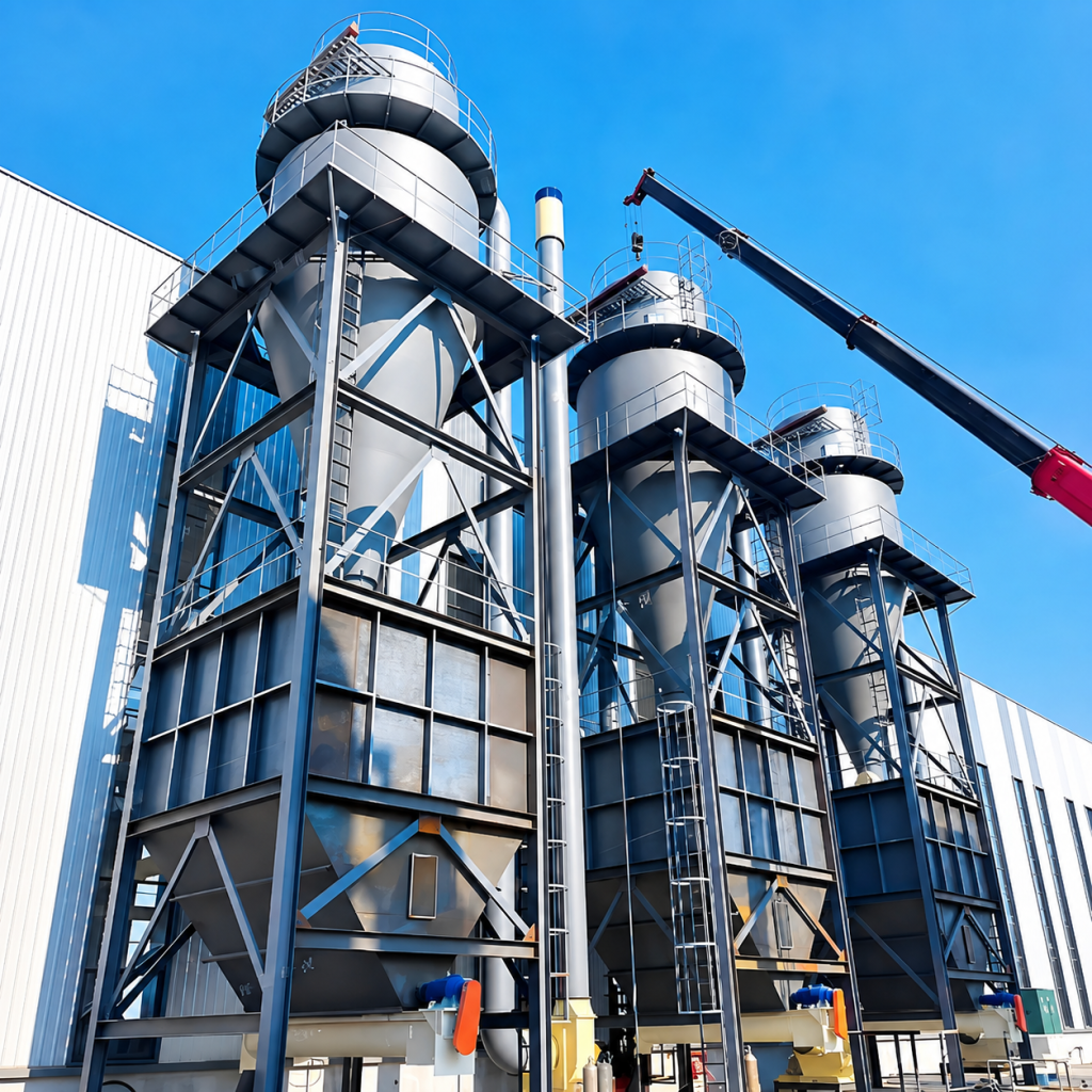
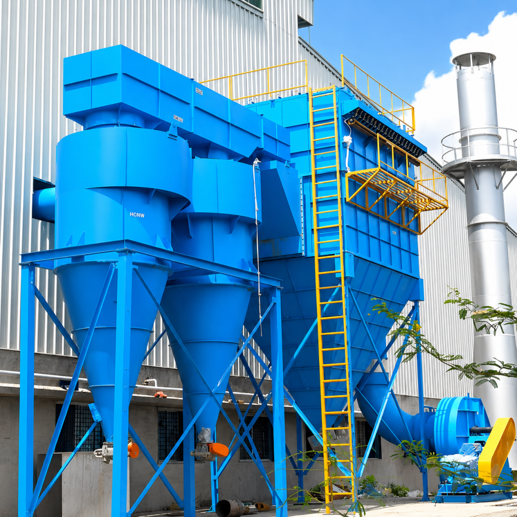
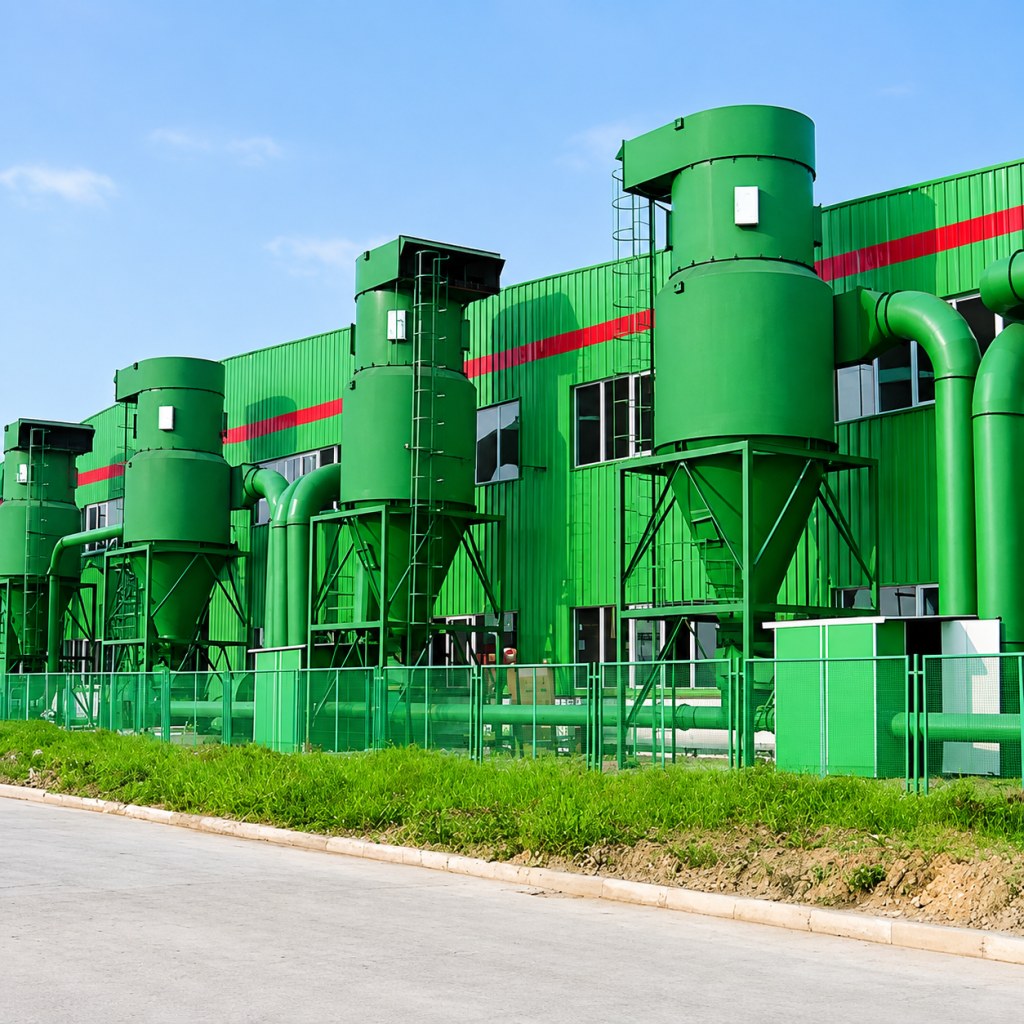
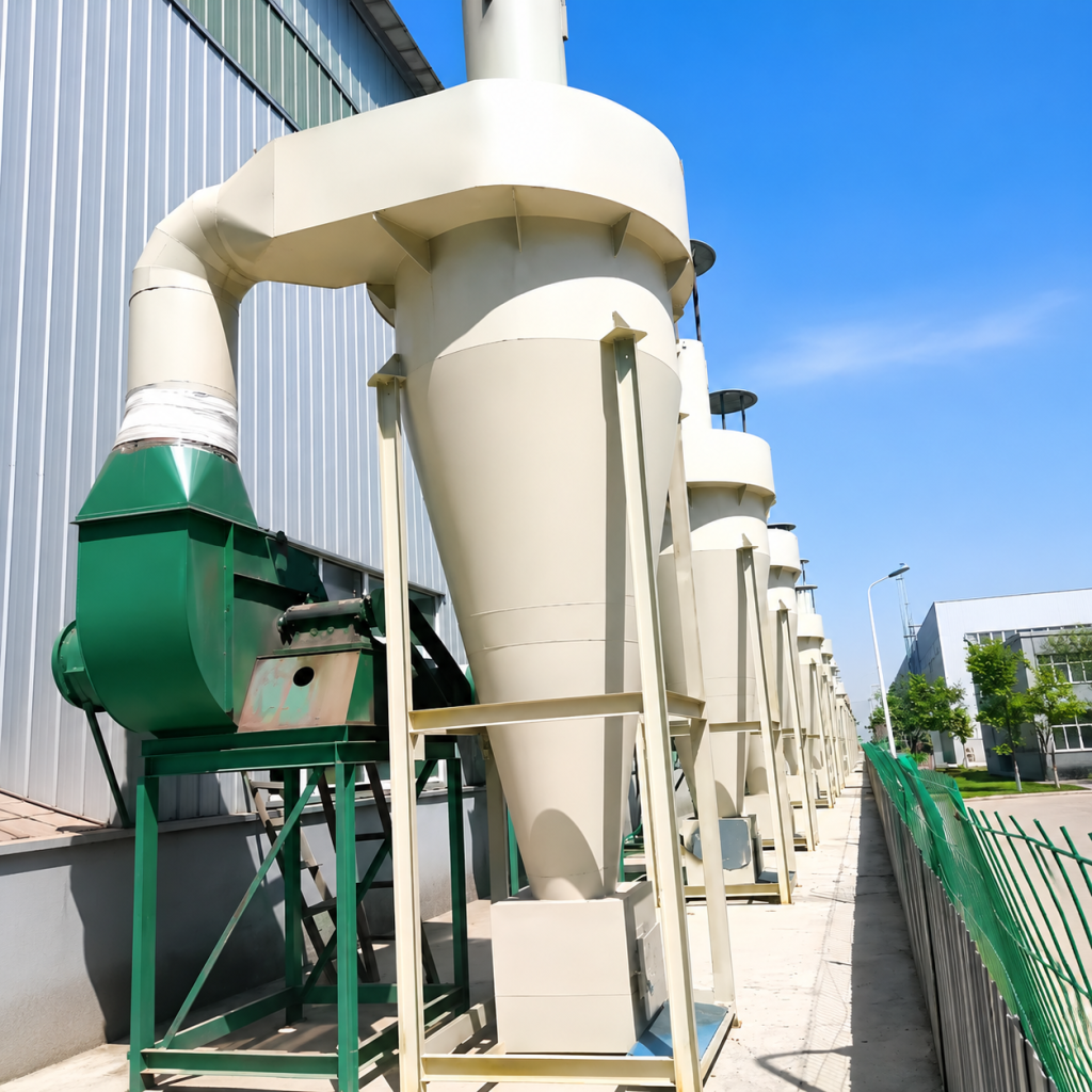
Mechanical centrifugal separation; coarse dust pretreatment; high-temperature flue gas adaptation.
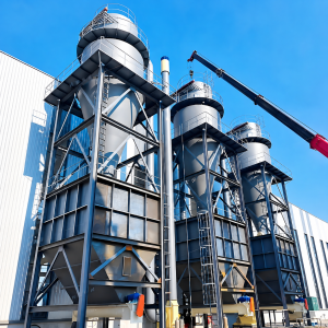
Cyclone dust collectors are mechanical dust removal devices that use the centrifugal force generated by the rotation of airflow to separate dust particles from the dust-laden airflow. The equipment consists of an inlet pipe, an outlet pipe, a cylindrical body, a conical body, and a dust hopper. It has no filter media and no moving parts, resulting in a simple structure, low maintenance, and low investment.
Classification dust removal efficiency (typical operating conditions):
Particle size ≥20 μm: 95%–99%
Particle size 10–20 μm: 85%–95%
Particle size 5–10 μm: 50%–80%
Particle size <5 μm: <50% (Recommended for use with bag or cartridge dust collectors)
Segmentation particle size d₅₀: 5–15 μm (Depending on the model and inlet velocity; the removal rate for this particle size is approximately 50%) The equipment is widely used in the pretreatment of coarse dust, high-temperature flue gas purification and the pre-processing stage of multi-stage dust removal systems. It can effectively reduce the load on downstream fine dust removal equipment and extend the service life of filter media.
Dust-laden gas enters the cyclone separator tangentially at a speed of 12–25 m/s, forming a strong rotating outer vortex within the cylinder and cone. Dust particles are thrown against the cylinder wall by centrifugal force, and after collision, slide down the wall surface by gravity into the ash hopper. The purified gas forms an upward inner vortex at the center and is discharged through the exhaust pipe. A sealed ash discharge device (star-shaped discharge valve or double-layer flap valve) is installed at the bottom of the ash hopper for periodic or continuous ash discharge, preventing the settled dust from being re-entrained.
Process Flow:
Dust-laden gas inlet → Tangential entry into cyclone separator → External vortex centrifugal separation → Dust settling into ash hopper → Clean gas discharge from internal vortex → Ash discharge from ash hopper
Applicable Dust:
Metal shavings, ore particles, coarse sawdust, grain particles, limestone powder, cement raw materials, fly ash, grinding dust, and other non-fibrous, non-sticky, and non-hygroscopic dust.
Applicable Industries:
Metallurgy, mining, coal, chemical, building materials, power, grain processing, wood processing, foundry sand treatment.
Recommended Process Combinations:
Cyclone + bag filter, cyclone + cartridge filter, cyclone + electrostatic precipitator, cyclone + wet desulfurization.
Not Applicable Scenarios:
Standalone treatment of highly sticky, fibrous, and hygroscopic dust, as well as fine dust with a high proportion of particles <5 μm.
Determine the initial diameter based on the air volume.
The recommended air volume for a single cylinder is no more than 35,000 m³/h. For extremely large air volumes, multiple cylinders connected in parallel or in an array arrangement are preferred to maintain high separation efficiency.
Material Selection Based on Dust Characteristics
Conventional Dust: Q235B carbon steel with rust-proof surface treatment
Corrosive Flue Gas: SS304 / SS316L stainless steel
High-Temperature Flue Gas (400–800℃): Heat-resistant steel + refractory brick/castable lining
Highly Abrasive Dust (quartz sand, mineral powder): Ceramic sheet lining, silicon carbide, or wear-resistant cast iron
Process Combination Based on Emission Requirements
Coarse dust removal/material recovery only: Single-stage cyclone is sufficient
Achieving emission standards (≤30 mg/m³): Cyclone + bag filter/cartridge filter (cyclone removes over 80% of coarse particles, reducing downstream load)
Ultrafine Dust (high proportion <5 μm): Bag filter or electrostatic precipitator is recommended; cyclone only for pre-treatment protection
Installation Site: A top maintenance space (≥500 mm) and ash hopper discharge channel must be reserved; lifting hooks are recommended on the top of the equipment; recommended plant height ≥6 m (XFC-2000 type).
Foundation Requirements: Concrete foundation flatness ≤3 mm/m; vibration damping pads are recommended for large equipment (≥Φ1600).
Insulation Requirements: When handling high-temperature, humid flue gas, the cylinder and ash hopper outer walls must be insulated to prevent condensation and ash adhesion.
Ash Discharge Sealing: The ash hopper must be equipped with a reliable airlock device (star-shaped discharge valve or double-layer flap valve). For every 1% increase in air leakage, dust removal efficiency may decrease by 2%–5%.
Regular Inspection: Quarterly inspections should be conducted on cylinder wall wear (especially below the air inlet and the cone transition section), ash discharge valve blade clearance, and lining thickness.
|
Features |
Technical Description |
|
Filter Bag-Free Design |
No filter bags required, eliminating the need for filter bag replacement. No vulnerable parts such as pulse valves, resulting in low maintenance costs. |
|
High Temperature Resistance |
Standard carbon steel type suitable for temperatures ≤400°C; internal heat-resistant materials (fire-resistant bricks, ceramics, heat-resistant castables) can withstand temperatures up to 800–1000°C. |
|
High Concentration Adaptability |
Capable of treating gas containing dust concentrations up to 1000 g/m³; commonly used as a pre-treatment system before bag filters or electrostatic precipitators. |
|
Moderate Pressure Drop |
Operating pressure drop: 500–2500 Pa. No additional compressed air consumption (lower energy consumption compared with pulse-jet bag filters). |
|
Dry Dust Discharge |
No water pollution; convenient recovery of valuable metal cutting particles, mineral powder, and other materials. |
|
Parallel Expansion Capability |
Multiple units can be connected in parallel for large air volume treatment, without affecting the efficiency and pressure drop of individual systems. |
|
Optional Wear Resistance |
The cylinder body can be lined with ceramic tiles, silicon carbide, or wear-resistant cast iron, making it suitable for highly abrasive dust such as quartz sand and mineral powder. |
|
Parameter Item |
Unit |
XFC-300 |
XFC-500 |
XFC-800 |
XFC-1200 |
XFC-1600 |
XFC-2000 |
|
Cylinder Diameter |
mm |
Φ300 |
Φ500 |
Φ800 |
Φ1200 |
Φ1600 |
Φ2000 |
|
Processing Air Volume |
m³/h |
670–1000 |
1500–2500 |
4000–6000 |
8000–12000 |
15000–22000 |
25000–35000 |
|
Inlet Air Velocity |
m/s |
12–18 |
12–20 |
15–22 |
15–25 |
15–25 |
15–25 |
|
Equipment Pressure Drop |
Pa |
500–1200 |
600–1500 |
800–1800 |
1000–2000 |
1000–2200 |
1200–2500 |
|
Inlet Dust Concentration |
g/m³ |
≤500 |
≤800 |
≤1000 |
≤1000 |
≤1000 |
≤1000 |
|
Particle Separation Size (d₅₀) |
μm |
5–8 |
5–8 |
5–10 |
5–10 |
5–12 |
5–15 |
|
Equipment Height |
mm |
1200 |
1800 |
2500 |
3000 |
3800 |
4500 |
|
Reference Weight |
kg |
~80 |
~200 |
~600 |
~1500 |
~3500 |
~6500 |
|
Operating Temperature |
°C |
≤400 |
≤400 |
≤400 |
≤400 |
≤400 |
≤400 |
|
Item |
Standard / Requirement |
|
Material Standard |
Shell: Q235B (GB/T 700) or SS304/SS316L (ASTM A240); wear-resistant lining: Al₂O₃ ceramic or high-chromium cast iron |
|
Welding Standard |
Key welds shall comply with GB/T 985.1 / AWS D1.1 standards; 100% visual inspection of weld seams; 20% PT (Liquid Penetrant Testing) inspection for critical welds |
|
Air Tightness |
Negative pressure air tightness test before delivery; leakage rate ≤3% |
|
Surface Treatment |
Shot blasting to Sa2.5 grade; epoxy-rich primer + topcoat; coating thickness ≥80 μm |
|
Warranty Period |
Self-inspection and acceptance warranty period: 12 months. During the warranty period, free repair or replacement will be provided for failures caused by material defects or manufacturing process issues |
Note:
Shot blasting, metallurgy, cement, power generation, chemical processing, mining, woodworking, machinery manufacturing, glass production, grain deep processing, and other mainstream manufacturing industries worldwide.
The system can process shot blasting scale, grinding dust, welding fume, boiler fly ash, cement raw meal, chemical powders, and food-grade particles. It is commonly supplied with shot blasting machines, grinding machines, crushers, sandblasting rooms, and polishing lines, and is a standard dust-control solution for heavy industry and automotive component factories.
The efficiency of a cyclone dust collector is strongly correlated with particle size:
• Particle size ≥20 μm: Removal rate 95%–99%
• Particle size 10–20 μm: Removal rate 85%–95%
• Particle size 5–10 μm: Removal rate 50%–80%
• Particle size <5 μm: Removal rate is typically <50%
Therefore, cyclone dust collectors are suitable for pretreatment of coarse particles, but not for the individual emission of fine dust to meet standards.
Sticky dust easily adheres to the cylinder wall, forming scale, increasing resistance and reducing separation efficiency; fibrous dust easily clumps together, interfering with airflow distribution. For these two types of dust, bag filters, cartridge filters, or wet scrubbers are recommended.
Conventional carbon steel structures have a temperature resistance of ≤400℃. Linings made of refractory materials (refractory bricks, ceramics, heat-resistant castables) can withstand temperatures up to 800–1000℃. A safety margin of ≥50℃ should be allowed when selecting a model. For high-temperature operating conditions, the thermal expansion of the cylinder and the sliding compensation of the supports need to be checked.
Cyclone dust collectors can remove more than 80% of coarse dust particles, significantly reducing the load on subsequent bag filters or electrostatic precipitators, extending the life of filter media/plates, and reducing overall operating costs. Common combinations: cyclone + bag filter, cyclone + electrostatic precipitator, cyclone + cartridge filter.
Main methods: Optimize the inlet design to ensure uniform airflow distribution; appropriately reduce the cylinder diameter (small diameter, high-efficiency type); lengthen the cone to increase separation time; use multiple pipes in parallel; ensure good sealing of the ash hopper to prevent secondary dust generation; control the inlet air velocity within the optimal range of 15–22 m/s.
Taking the XFC-1200 model as an example, the equipment diameter is Φ1200 mm, the height is approximately 3000 mm, and including the ash hopper and maintenance space, it occupies approximately 12–16 m². The XFC-2000 model occupies approximately 25–30 m². Space must be reserved for top hoisting and side maintenance access during installation.
Cyclone dust collectors do not have conventional vulnerable parts such as filter media, making them low-maintenance equipment. Main inspection items include: cylinder wall wear (the area below the inlet and the transition section of the cone are high-wear zones), ash discharge valve sealing, and dust accumulation in the ash hopper. When handling abrasive dust, it is recommended to use a wear-resistant lining. Check the lining thickness every 3–6 months; replace it immediately if wear exceeds 50%.
Please provide: air volume (m³/h), inlet dust concentration, dust type and particle size distribution, flue gas temperature, emission requirements, installation site dimensions and power supply conditions, and whether a high-temperature resistant/wear-resistant lining/stainless steel material is required. We offer free selection calculations and solution design.

English

Hindi

Indonesian

Russian

Spanish

Thai

Vietnamese