Global Surface Treatment Equipment & System Solutions — Since 2002

久昌机械
Get a Quote
Global Surface Treatment Equipment & System Solutions — Since 2002
久昌机械
Specialized equipment for high-efficiency surface cleaning of wire workpieces
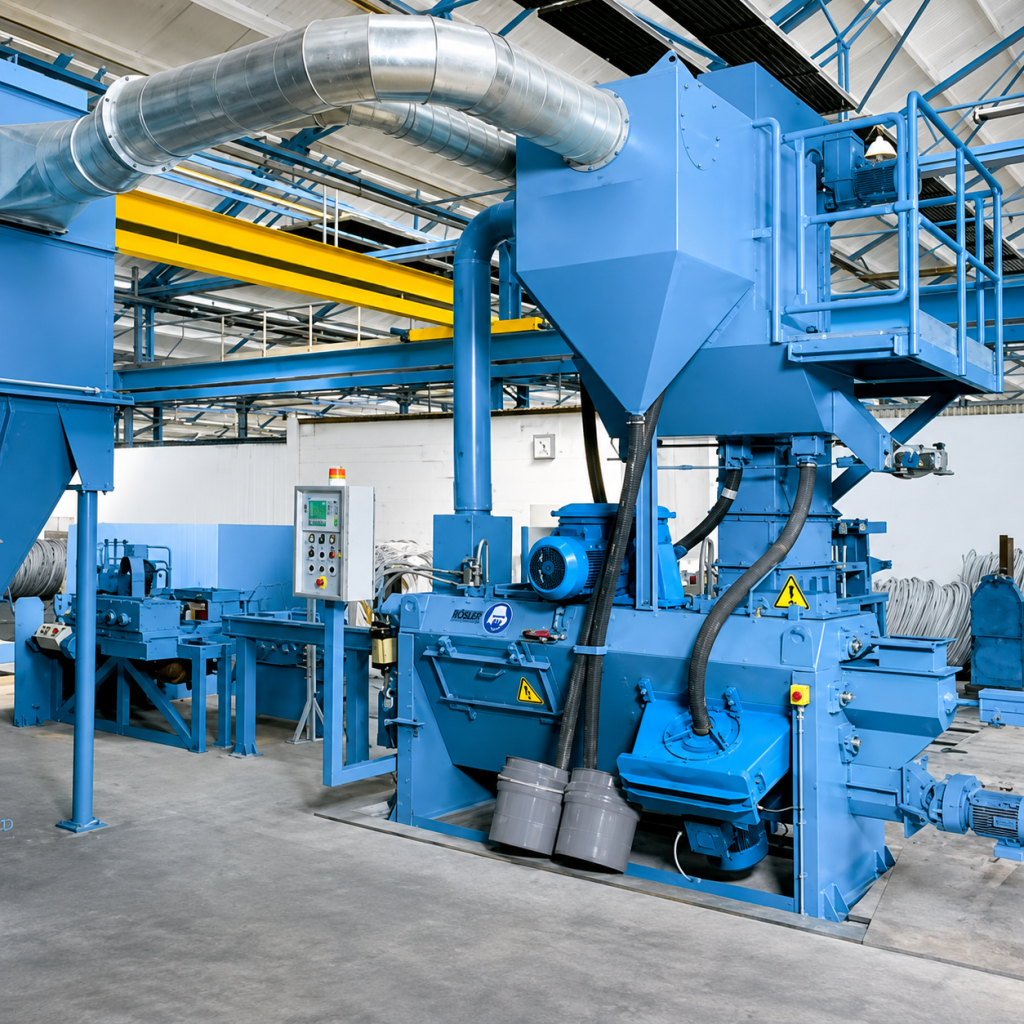
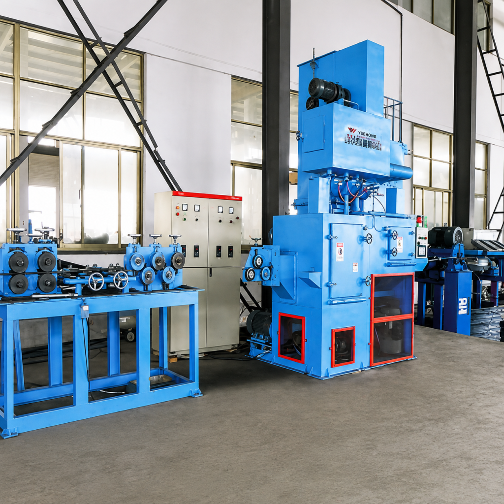
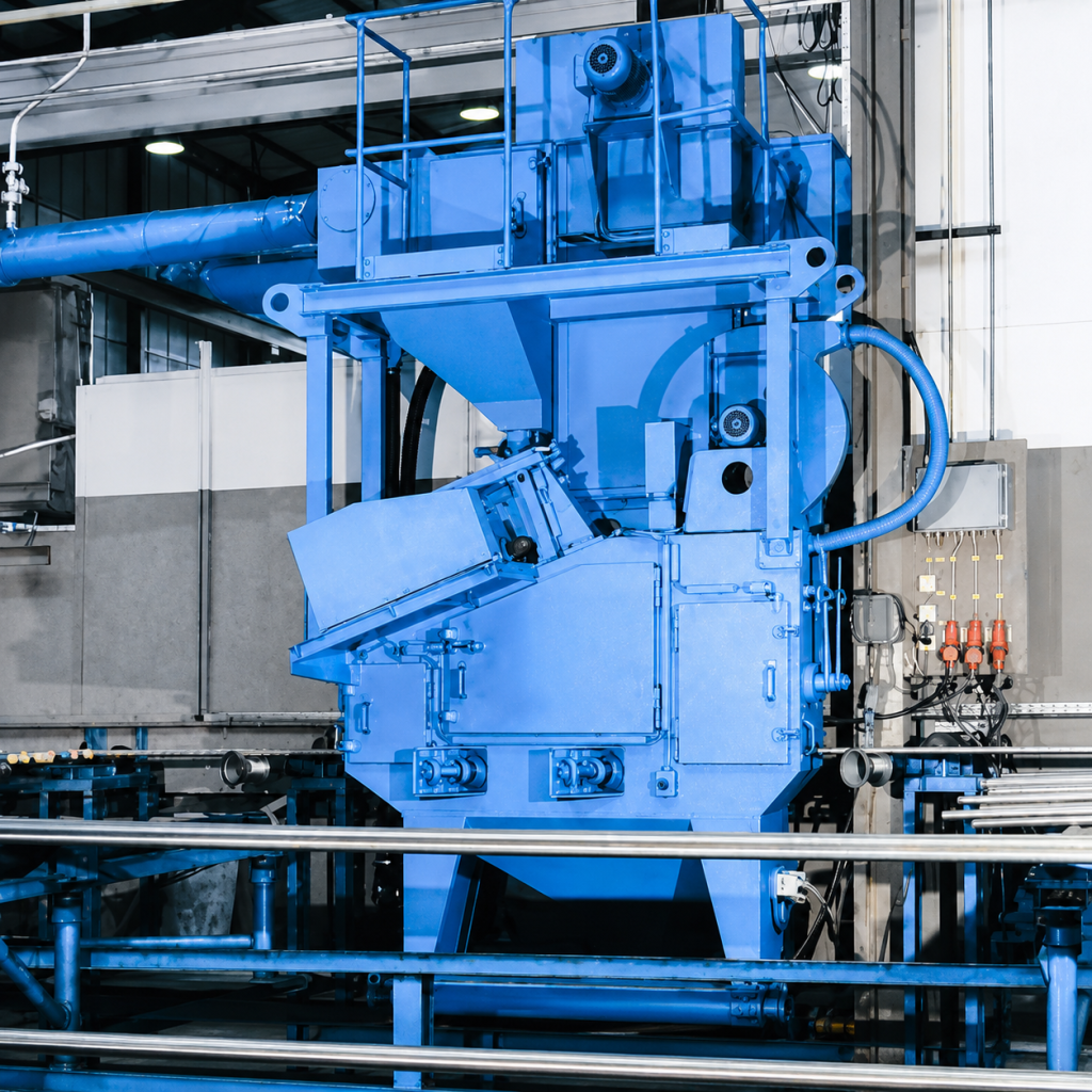
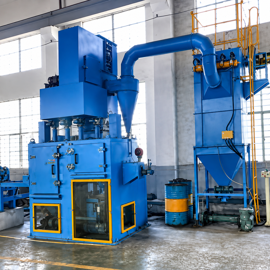
The QGW series linear through-feed shot blasting machine is a specialized continuous through-feed device designed for surface cleaning and strengthening of wire rods such as coiled steel bars, wire rods, steel strands, and wire ropes. After being uncoiled by the uncoiling device, the coiled steel wire is guided by a set of guide wheels and continuously passes through a closed shot blasting chamber at a constant linear speed. Multiple shot blasters blast the wire surface at high speed from multiple angles, achieving rust removal, oxide scale removal, and surface strengthening. The equipment supports continuous production line operation, has a high degree of automation, and can be integrated with uncoiling machines, take-up machines, and length-cutting machines to form a complete production line. The surface cleanliness after treatment can reach Sa2.5 level (ISO 8501-1), and the roughness Rz 25–60 μm (depending on the abrasive type and process parameters).
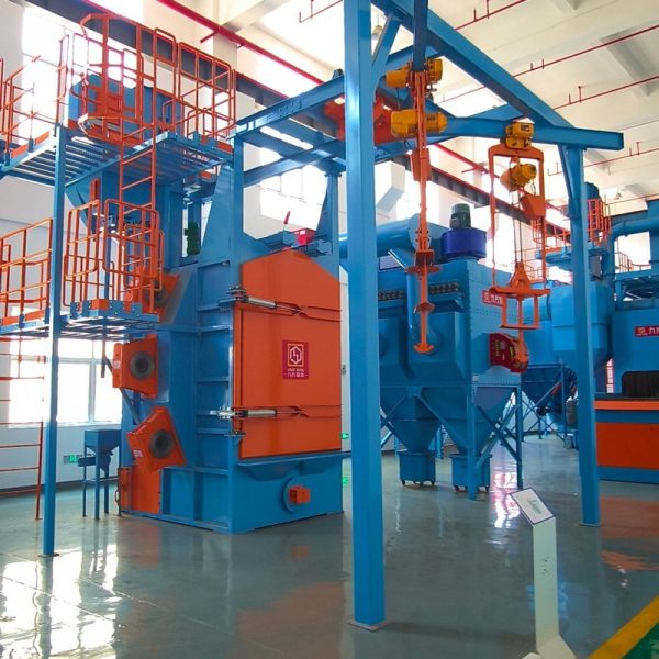
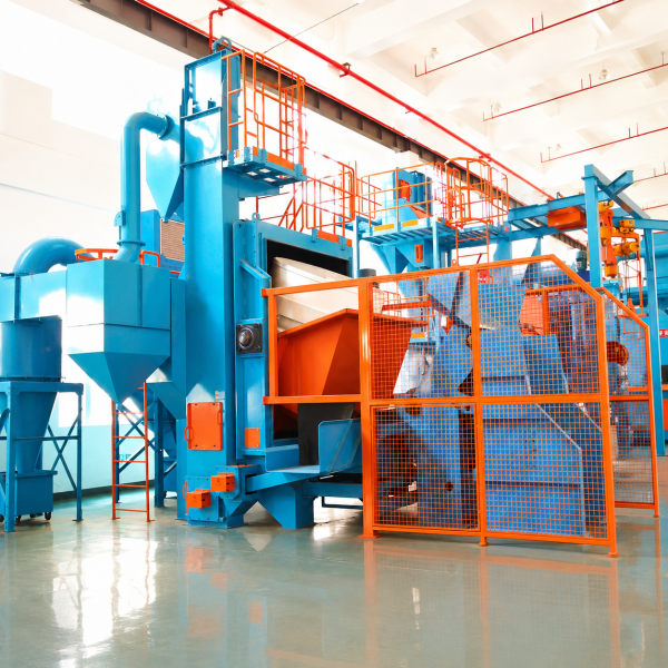
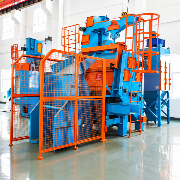
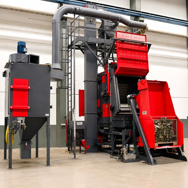
After being unwound and unloaded by the unwinding device, the coiled steel wire is guided into the shot blasting chamber by a set of fastening guide wheels. Multiple shot blasters are arranged around the chamber at three-dimensional simulated angles, and the shot impacts the wire surface at high speed from various angles, causing oxide scale and rust to fall off. The shot then passes through a scraper recovery system at the bottom of the chamber, a screw conveyor, and a bucket elevator into an air separator for separation and recycling. Dust and broken shot are filtered by a pulse jet filter/bag filter system before being discharged in compliance with standards. The cleaned wire is then coiled and wound or cut to length by the winding device.
Process Flow: Unwinding and Unwinding → Guide Wheel Conveying → Shot Blasting → Shot Cleaning → Winding and Rewinding/Cutting to Length → Unloading
The shot blasting machine adopts a high-efficiency direct-drive structure, with a direct-drive motor and no belt transmission. The impeller is 100% dynamically balanced (dynamic balance grade G6.3) to ensure vibration ≤4.5 mm/s at high speeds. The blades, shot distribution wheel, directional sleeve, and guard plates are all made of high-chromium wear-resistant cast iron, with a chemical composition conforming to ASTM A532 standard and a hardness ≥58 HRC.
Shot blasting machine: High-efficiency direct-drive type, with layout angle optimized by 3D simulation to ensure full circumference coverage of the shot;
Guide roller assembly: Quenched alloy steel guide rollers, surface hardness HRC 50–55, bearings are sealed and dustproof, life 6000–10000 h;
Chamber lining plate: High-chromium cast iron/65Mn rolled lining plate, modular quick-connect design, thickness 10–15 mm, quick replacement;
Shot circulation system: Bottom scraper recovery + screw conveyor + bucket elevator + air separation, separation efficiency ≥99%, ensuring shot purity;
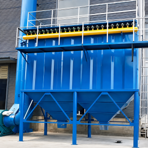
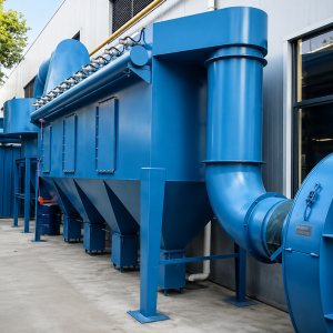
Dust removal system: Standard pulse cartridge dust collector (bag filter optional), dust emissions can be controlled to <5 mg/m³;
Electrical system: PLC control (Siemens/Mitsubishi optional), touch screen operation, supports automatic/manual modes, adjustable linear speed frequency conversion, optional remote monitoring module.
Installation Site Requirements:
The QGW20 model occupies approximately 18 m × 4 m (including the cable laying area, main unit, and cable take-up area), with a factory height ≥ 6 m;
The QGW50 model occupies approximately 28 m × 5 m, with a factory height ≥ 7 m; Both the cable laying and take-up areas require reserved space for cable reel rotation, with a recommended ≥ 3 m on each side;
The concrete foundation flatness must be ≤ 3 mm/m, and anchor bolts must be pre-embedded in the main unit area;
Power supply: 380V/3Ph/50Hz (or customized according to customer's power grid), requiring a total equipment power capacity + 20% margin.
Maintenance Points
Daily: Check the operating sound, vibration, and current of the shot blasting machine; check the rotation flexibility and wear of the guide rollers; check the integrity of the sealing curtain;
Weekly: Check the wear of vulnerable parts (blades, guard plates) and replenish lubricating grease; check the tension of the elevator belt/chain;
Every 3–6 months: Conduct a comprehensive inspection of the chamber guard plates and guide roller groove wear; check the position of the shot blasting machine's directional sleeve window; check the pressure difference of the dust collector filter cartridge/bag;
Blade Replacement Standard: Replace blades when wear >5 mm or cracks appear to ensure that the blasting speed does not decrease;
Guide Roller Replacement Standard: Replace guide rollers when the wear depth of the guide roller groove is >2 mm or the bearing clearance exceeds the standard to prevent wire slippage or scratches.
Jiuchang Machinery possesses independent import and export rights, offering various trade terms such as FOB/CIF/DDP, and supporting letters of credit, wire transfers, and milestone payments. Overseas installation services include a three-tiered model: remote technical supervision, on-site installation guidance, and turnkey projects. Global 24/7 response: over 80% of common faults can be resolved within 4 hours via remote diagnostics; local engineers arrive on-site within 48 hours. Commonly used spare parts from core market warehouses are delivered within 48 hours.
|
Parameter Items |
Unit |
QGW20 |
QGW30 |
QGW40 |
QGW50 |
|
Processing wire diameter |
mm |
Φ5–20 |
Φ5–25 |
Φ6–32 |
Φ8–40 |
|
Processing line speed |
m/min |
65–120 |
65–120 |
65–100 |
50–80 |
|
Reference daily output |
t |
60–100 |
80–120 |
100–150 |
120–200 |
|
Number of shot blasting machines |
tower |
4 |
6 |
6–8 |
8 |
|
Power of a single shot blasting machine |
kW |
11 |
11 |
15 |
15 |
|
Total power of shot blasting machine |
kW |
44 |
66 |
90–120 |
120 |
|
Bullet diameter |
mm |
Φ0.6–1.2 |
Φ0.6–1.2 |
Φ0.8–1.5 |
Φ0.8–1.5 |
|
Elevator lifting capacity |
t/h |
30 |
40 |
50 |
60 |
|
Separator separation volume |
t/h |
30 |
40 |
50 |
60 |
|
Dust removal air volume |
m³/h |
8000 |
12000 |
15000 |
20000 |
|
Cleaning chamber dimensions (length × width × height) |
mm |
4000×400×600 |
5000×400×600 |
6000×450×700 |
7000×500×800 |
|
Total installed power (excluding dust removal) |
kW |
≈52 |
≈78 |
≈100 |
≈125 |
|
Total installed power (including dust removal) |
kW |
≈65 |
≈95 |
≈125 |
≈155 |
Suitable for surface cleaning and strengthening of wire rods such as coiled steel bars, wire rods, high-strength low-relaxation steel strands, prestressed steel wires, and steel ropes. Widely used in industries such as building reinforcement, bridge cables, steel strand manufacturing, steel rope production, and metal products.
Processable wire specifications:
Diameter range: Φ5–40 mm (depending on model)
Material: Carbon steel, low-alloy steel, stainless steel wire (abrasive type adjustment required)
Form: Coiled wire, straight passage
Not suitable for: Wires coated with oil film or with adhesive substances (pre-cleaning required)
Coil processing directly processes the coil in its round state, eliminating the need for unwinding and rewinding, saving equipment and space. It maintains the round shape after processing, making it suitable for scenarios with moderate surface quality requirements or where coils need to be stored and transported in their round state. Straight-through processing requires straightening the wire before passing it through, resulting in faster processing speed and higher efficiency, but it requires a matching unwinding and rewinding unit. It is suitable for high-volume continuous production and scenarios with high surface quality requirements. The two types can complement each other: coil processing is used for coil pre-processing, while straight-through processing is used for finishing lines.
It can process coiled steel bars and wire rods weighing 300–2500 kg and with an outer diameter of Φ600–1500 mm. By adjusting the specifications of the workstation frame and the spacing of the guide rollers, it can accommodate different coil diameters and weights. For extra-large coils exceeding this range, a dedicated workstation frame and a larger cleaning chamber can be customized.
The processing cycle (shot blasting + blowing) depends on the coil weight, degree of corrosion, and cleaning requirements, generally 5–15 minutes per coil. Taking QGP1000 (1 ton coil weight, 8 minutes/coil) as an example, with alternating double-station operation and an 8-hour shift, the daily output is approximately 30–50 tons; a two-shift system (16 hours) can reach 60–100 tons. Actual output is related to shift start time, worker skill level, and equipment utilization.
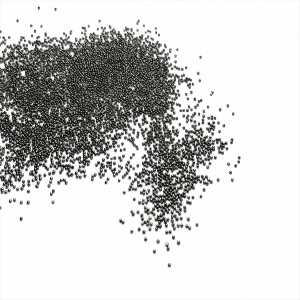
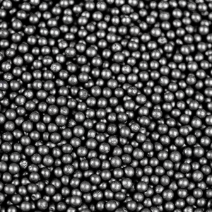
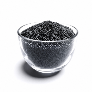
For whole-coil processing, fine steel shot or shredded shot with a diameter of Φ0.8–1.5 mm is generally used, requiring good flowability to enter the coil gap.
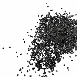
Carbon steel wire: Cast steel shot/shredded shot, hardness HRC 40–50;
Stainless steel wire: Stainless steel shot, avoiding iron ion contamination;
The shot diameter should be less than 1/3 of the wire gap to ensure effective entry into the inner layer of the coil. The shot can be configured according to the wire diameter, material, and cleaning grade requirements.
Under standard operating conditions, the surface cleanliness can reach Sa2.5 (ISO 8501-1), with a roughness Rz of 25–60 μm. Because the inner layer of wire is obscured by the outer layer during whole-coil processing, the cleanliness of the inner layer may be slightly lower than the outer layer. If both the inner and outer layers of the whole coil need to reach Sa2.5, this can be achieved by extending the processing time or increasing the number of shot blasters. For whole-coil rust removal of construction rebar, Sa2.0–Sa2.5 is usually sufficient to meet the subsequent concrete bond strength requirements.
Main vulnerable parts include shot blaster blades, shot distribution wheel, directional sleeve, chamber guard plate, workstation frame wear-resistant plate, and sealing curtain.
High-chromium cast iron blades: Standard operating conditions 2500–3000 h;
Chamber liner: 3000–8000 h (depending on abrasive impact angle);
Workstation frame wear-resistant plate: 4000–6000 h;
Sealing curtain: 6–12 months.
We provide a standardized spare parts list and global spare parts warehousing and distribution services.
Yes. The cleaning chamber size, workstation frame specifications, number and arrangement angle of shot blasters, conveyor system speed, etc., can all be customized according to the user's pan weight, pan diameter, and production requirements. We provide free operating condition diagnostics, 3D simulation, and solution design services.
Please provide: wire type and diameter range, pan weight and diameter range, daily or annual production capacity requirements, target cleaning grade (Sa2.5/Sa3), plant size and power supply conditions, whether auxiliary loading/unloading equipment is required, and local environmental emission standards. We offer personalized technical solutions and formal quotes.

English

Hindi

Indonesian

Russian

Spanish

Thai

Vietnamese